


What makes a corrugated roof look convincing on a railway model: the profile, the overlap, or how the panels sit against the frame? All three matter when modelling corrugated iron buildings. A convincing finish depends on getting the sheet pattern and construction in proportion.
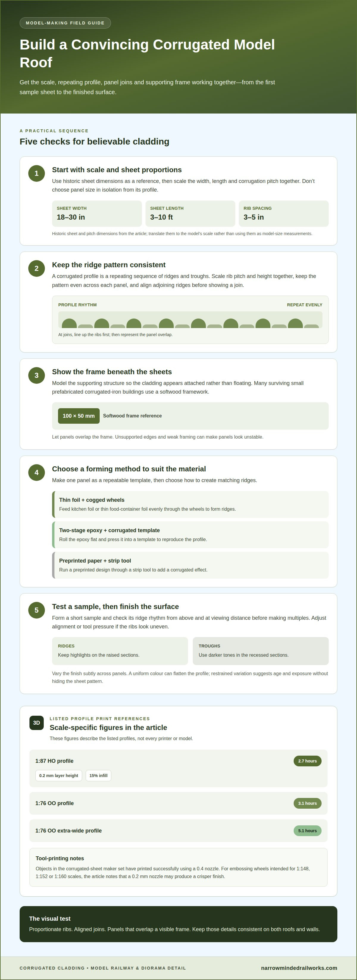
Historic sheets were typically 18-30 inches wide and 3-10 feet long, with corrugations spaced 3-5 inches apart. At model scale, these dimensions help guide the panel size and profile, while the material and method you choose affect how neatly the cladding can be cut, shaped and joined.
It’s easy to focus on the roof, but corrugated panels also add texture to walls, railway structures and diorama buildings. This guide explains how scale affects sheet dimensions, what to consider when choosing a profile, and how simple materials and tools can recreate the ridged surface.
You’ll also learn how corrugated iron was used for huts and shelters, and how to apply the same modelling principles to railway scenes and dioramas.
Key Takeaways
- Use scale and corrugation profile together to keep panels looking proportionate, rather than choosing sheet dimensions in isolation.
- Overlap cut panels to create convincing roofs, and consider corrugated sheeting for walls as well as roofing.
- Choose a forming method to suit the finish you want, from thin foil shaped with a corrugating tool to epoxy pressed into a template.
- For narrow-gauge layouts and dioramas, explore suitable kits and scenery from Narrow Minded Railworks to support the wider scene around your buildings.
Typical sheet sizes, profiles and construction
Historic sheets commonly measured 18-30 inches wide and 3-10 feet long. Their dimensions and rib spacing provide useful starting points for scale models.
Sheet dimensions and profile choices
A corrugated profile is a repeated series of ridges and troughs pressed into sheet material. Its width, length and pitch affect how a model roof reads, so scale each dimension consistently. Corrugation pitch and sheet thickness affect how a model roof reads, so consider both when choosing a profile. These measurements help distinguish broad, shallow profiles from narrow, pronounced ridges.
Construction matters too. Many surviving small prefabricated corrugated-iron buildings use a softwood framework measuring 100 x 50 mm. Model the supporting frame beneath the cladding, then let the panels overlap it. That small structural detail helps explain how the roof and walls meet, rather than making the sheets appear to float.
Accurate corrugation geometry
Accurate geometry means scaling the rib pitch and height together, not merely drawing parallel lines. A 3-5-inch historic pitch becomes a much finer repeated pattern at railway scale. Keep the profile consistent across adjoining panels, and align their ridges before representing overlaps. Otherwise, even correctly sized sheets can look uneven when assembled.
For printed profiles, the listed 1:87 HO design uses a 0.2 mm layer height and 15% infill. Its estimated print time is 2.7 hours. The listed 1:76 OO profile takes 3.1 hours, while its extra-wide version takes 5.1 hours. These figures describe the listed profiles, not every printer or model.
Condensation can collect behind cladding where moisture meets limited airflow, and dampness can contribute to corrosion. Unsupported edges and weak framing can also leave panels unstable, so make the frame and sheet overlaps clear in your model.
UK examples include Henry Robinson Palmer’s corrugated-iron-roofed shed at London docks, spanning 40 feet, and a prefabricated iron palace displayed publicly in Liverpool in 1845. For supplier details, compare technical drawings for sheet width, pitch, thickness, fixing and overlap. These specifications help translate a real profile into a consistent model.
Model railway and diorama building cladding
For railway models and dioramas, corrugated panels can clad roofs and walls. Architectural plans prioritise dimensions; 3D renders show surface and lighting, while scale models must make texture readable at close range.
Roof and wall detailing
Roof and wall detailing means arranging panels, seams and fasteners to show how the cladding meets its frame. These details make a building look assembled rather than covered with one flat sheet. Cut corrugated panels to fit, then overlap their edges to suggest roofing. On walls, align panel edges consistently and mark where separate sheets meet. Add subtle fixing marks along the supports, scaled to suit the model.
In a 3D building model, insulation belongs behind the metal cladding, not on its visible surface. Show the separate layers in a cutaway or architectural plan; a scale model can suggest the same build-up through a discreet interior lining.
Realistic weathering and surface texture
Realistic weathering uses surface variation to make corrugations read clearly in a 3D render or physical scene. Keep highlights on ridges and darker tones in troughs, then vary the finish across individual panels. A uniform colour can flatten the profile, while restrained differences help suggest age and exposure without obscuring the sheet pattern.
Keep one cut corrugated panel as a template for making matching sheets. Feed kitchen foil or thin foil from food containers through cogged wheels to form ridges. Alternatively, roll two-stage epoxy flat and press it into a corrugated template. Both methods can also recreate other surfaces and textures.
In dioramas, use formed sheets for both walls and roofing, and overlap panels where the roof needs a joined appearance. A preprinted paper design can also gain a corrugated effect when run through a strip tool. Diorama Tools & Scenery can support projects that need textured scenery alongside model buildings.
How to model corrugated metal sheets and their corrugation accurately
Accurate corrugation depends on repeating a consistent ridge-and-trough pattern. Begin with the chosen model scale, such as 1:87 HO or 1:76 OO. Keep ridge spacing and depth consistent across each panel. At joins, align the pattern before adding overlaps. This avoids broken-looking ribs where one sheet meets another. For smaller scales, reduce visual exaggeration so the profile remains believable.
Embossing wheels can form repeatable ridges in thin sheet material. Feed a strip evenly between the cogged wheels, keeping its edge straight. A corrugated panel can then act as a template for matching pieces. The V2 corrugated-sheet maker has a star-grip handle to help turn its rollers. This gives the modeller a clear grip while feeding material through.
Printing the tool also affects the result. All objects in the corrugated-sheet maker set have printed successfully using a 0.4 nozzle. For embossing wheels intended for 1:148, 1:152 or 1:160 scales, a 0.2 mm nozzle may produce a crisper finish. Choose the finer nozzle when small ridges need sharper definition, rather than adding exaggerated depth.
Check the profile against the finished panel before making multiples. Roll a short sample first, then inspect the ridge rhythm from above and at viewing distance. For a 1:148 wagon shed, for example, overly deep ribs can dominate the wall. Adjust feed alignment or tool pressure to correct uneven ridges before forming more sheets.
For digital modelling, build one corrugation and repeat it across the panel. Keep the end edges clean, then create a separate overlap where sheets join. This makes it easier to adjust the profile than modelling every ridge independently. For physical models, use the same reference profile for roof and wall pieces. Consistent panels help the structure read as one building.
Historic corrugated-iron sheets were typically 18-30 inches wide, a useful reference when judging panel proportions. Model railway corrugated sheets can be cut to size and overlapped to recreate roofing. The designer recommends feeding strips of kitchen foil or thin foil from food containers through the tool's cogged wheels to make corrugated sheeting.
The foil and epoxy methods for forming corrugated sheets can also mimic other surfaces and textures, extending their use beyond roofs and walls.
What materials and software are best for modelling corrugated iron buildings?
Choose a material to suit the model’s purpose: thin foil works well for formed cladding, while two-stage epoxy creates a firmer relief. Flexible foil readily follows a template for a small roof. A larger diorama wall may benefit from a more rigid panel. Your choice depends on whether fine surface detail, a stable shape or matching repeated sheets matters most.
To add bulk and rigidity to foil, join several layers with watered-down PVA glue. Let them settle together before shaping so the surface stays even. For epoxy, combine equal amounts of the two constituents and knead until the colour is consistent. Press the material into a corrugated template to give the panel a defined texture and firmer body.
For digital work, use CAD or 3D-modelling software that lets you control repeated geometry. Build a single ridge-and-trough unit, then repeat it across the sheet. Keep the panel edges separate from the corrugation pattern, so you can adjust overlaps without rebuilding the surface. For a rendered scene, add texture through lighting and surface variation; for a printable model, keep the profile as physical geometry.
Plan the frame and cladding as separate parts. A small prefabricated building may use a softwood framework measuring 100 x 50 mm. Representing that support helps explain where sheets attach and how corners meet. For a physical model, test one panel against its frame before making the remaining walls or roof. This catches fit problems early.
Material choice also affects the finish. Foil can reproduce thin sheet edges, while layered foil or epoxy can give panels extra body. In software, distinguish ridges with restrained highlights and troughs with darker shading. Keep the underlying profile consistent across adjoining pieces. For more scenery and tools to support a railway or diorama project, explore modelling tools and scenery.
Narrow Minded Railworks
Narrow Minded Railworks offers scale kits and scenery for railway and diorama projects, helping bring the wider setting together. Once your corrugated building has its profile, cladding and finish, consider how it fits into the surrounding trackside scene or industrial yard.
Its range includes OO9 Locomotive & Wagon Kits, GN15 Locomotive & Scenery Kits, O-16.5 / 7mm Scale Kits, and Diorama Tools & Scenery. These offerings can help you develop the layout around a corrugated hut, shed or shelter, while keeping the building’s materials and construction choices your own.
If scenery or a narrow-gauge setting is the next step in your project, explore Narrow Minded Railworks’ kits and tools. Get in touch with Narrow Minded Railworks to discuss your modelling plans.
Shape the next stage of your railway scene
Once the building’s form is settled, consider its role in the wider layout. Is it a working shed beside a narrow-gauge line, a shelter at the edge of a settlement, or the focal point of a standalone diorama? The answer can guide the surrounding details and help the structure feel at home in its setting.
Careful modelling corrugated iron buildings is one part of creating a scene with character. Narrow Minded Railworks offers OO9 Locomotive & Wagon Kits, GN15 Locomotive & Scenery Kits, and O-16.5 / 7mm Scale Kits to help develop the railway and its surroundings. Choose the scale and setting that suit your project, then build outward from the building.
If you’re ready to plan the next part of your layout, contact Narrow Minded Railworks. Your corrugated structure can become the starting point for a distinctive scene, shaped around the railway or diorama you want to create.
Frequently Asked Questions
What does modelling corrugated iron buildings involve?
Modelling a corrugated-clad structure means recreating its overall form and visible sheet pattern at model scale. Decide whether you’re building a complete structure, such as a trackside hut, or just a roof or wall within a wider scene. That choice guides how much interior framing, edge detail and surface variation to show.
What are the typical dimensions and profiles of corrugated iron sheets in the UK?
Historic corrugated-iron sheets typically measured 18-30 inches wide and 3-10 feet long, with a 3-5-inch corrugation pitch. Roofing sheets were typically 1.2 mm thick. These dimensions describe historic material, not a single profile for every building. For a model, use them as a reference for the characteristic sheet shape, then represent the proportions consistently at your chosen scale.