

What if the difference between a smooth-running narrow gauge masterpiece and a £95 puff of "magic smoke" is just 0.5 millimetres of heat-shrink tubing? You've likely spent over 30 hours meticulously assembling a white metal or brass kit, only to face the daunting task of squeezing a DCC decoder into a boiler that barely has room for its own ballast. It's a common frustration for UK modellers; the fear of a hidden short circuit or a messy solder joint often keeps perfectly good locomotives stuck on DC power forever.
You deserve a loco that glides across your points without a flicker, and this guide will show you exactly how to master wiring a kit-built locomotive for dcc. We'll move past the confusion of motor isolation and wire colour codes to ensure your installation is both electrically sound and physically compact. We're going to cover everything from testing your chassis for "stray" paths to professional soldering techniques that fit inside the tightest OO9 or O14 bodies. By the end of this tutorial, you'll have the confidence to convert any DC chassis into a reliable digital performer.
Key Takeaways
- Learn why hardwiring is essential for narrow gauge kits and which professional-grade, temperature-controlled soldering irons are required for a reliable finish.
- Master the critical process of electrical isolation to prevent "live" chassis components from causing terminal damage to your DCC decoder.
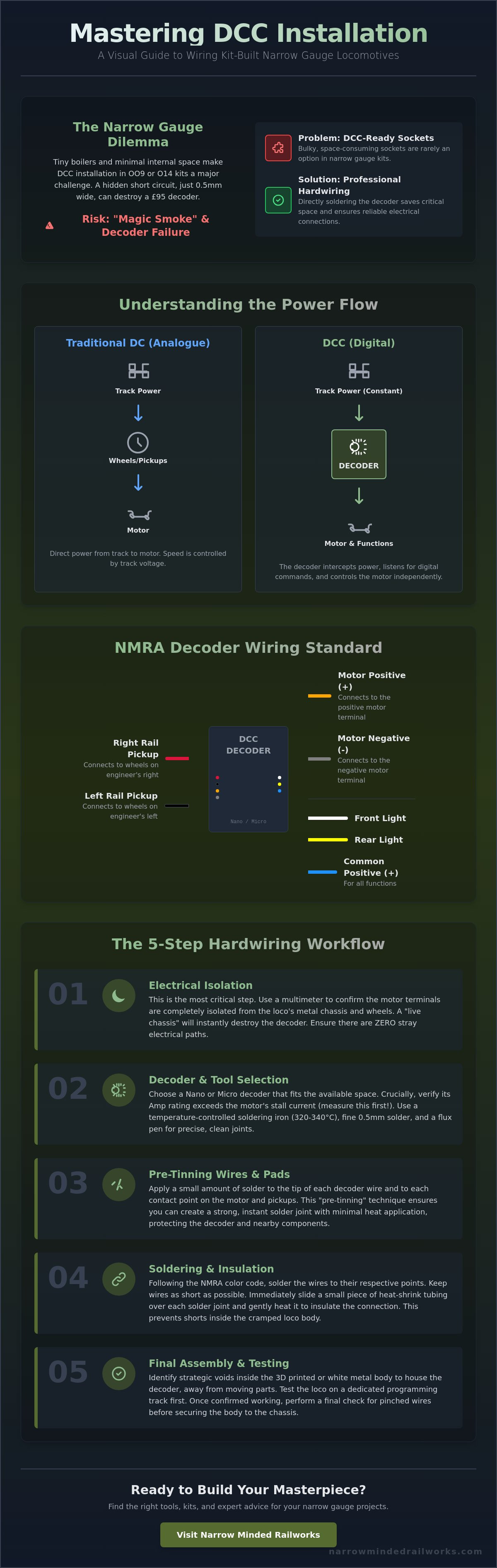
- Follow a professional step-by-step workflow for wiring a kit-built locomotive for dcc, including essential techniques like pre-tinning for secure electrical bonds.
- Discover how to identify strategic voids in 3D printed bodies to ensure your decoder fits perfectly without risking heat damage to resin or plastic parts.
- Understand how to select the ideal Nano or Micro decoder to suit the tight spatial constraints common in UK narrow gauge locomotive kits.
The Fundamentals of Wiring Kit-Built Locos for DCC
Building a locomotive from a brass or white metal kit is a rite of passage for many UK railway modellers. Unlike ready-to-run models from manufacturers like Hornby or Bachmann, which often feature "DCC-Ready" sockets, kit-built engines require a more hands-on approach. When you are wiring a kit-built locomotive for dcc, you won't find a convenient 8-pin or 21-pin plug waiting for you. Instead, you must interface directly with the raw components of the chassis.
The main difference lies in how the power flows. A DCC-Ready loco has a factory-installed circuit board that bridges the gap between the wheels and the motor until a chip is added. Kit-built locos are blank slates. You are responsible for creating the electrical path. Hardwiring is the permanent soldering of a decoder to a locomotive circuit. This method is often preferred in the kit-building community because it saves vital space inside cramped boiler barrels or side tanks where a bulky plastic socket simply won't fit.
The core logic of Digital Command Control (DCC) involves placing the decoder as a middleman. In a traditional DC setup, electricity travels from the rails, through the wheels, and directly into the motor. In a DCC system, the decoder intercepts this power. It listens for digital commands from your command station and then decides how much voltage to send to the motor. This allows multiple locomotives to sit on the same piece of track while responding to different instructions.
To better understand this concept, watch this helpful video:
The DCC Color Code Standard
Success when wiring a kit-built locomotive for dcc depends on following the NMRA standardised wiring colours. Most UK decoders, such as those from Gaugemaster or Zimo, adhere to these rules:
- Red and Black: These wires connect to the track pickups. Red usually goes to the right-hand rail and black to the left.
- Orange and Grey: These are the motor leads. Orange connects to the positive motor terminal and grey to the negative.
- Blue, White, and Yellow: These manage functions. Blue is the common positive for lights, while white handles the front light and yellow handles the rear.
Why Narrow Gauge Kits Require a Different Strategy
If you are working with OO9 or GN15 scales, the physical footprint of your model is significantly smaller than standard gauge equivalents. Understanding what is a narrow gauge railway helps explain why space is your biggest enemy. These kits often represent tiny industrial or mountain prototypes with very little internal volume.
You must balance the physical size of the decoder with the current requirements of the motor. A tiny "micro" decoder might fit inside a 009 tank engine, but you need to check its Amp rating. If an older white metal kit uses a motor that draws 0.8 Amps and your decoder is only rated for 0.5 Amps, you risk a permanent hardware failure. Always measure the motor's stall current before selecting your wiring components to ensure the decoder can handle the load without overheating.
Essential Tools and Decoder Selection
Success when wiring a kit-built locomotive for dcc starts with your workbench setup. You can't rely on a standard 40W hardware store iron for this level of precision. A temperature-controlled soldering station is mandatory. Set your iron to roughly 320°C or 340°C to ensure quick heat transfer without melting the plastic components of your chassis. Use 0.5mm diameter lead-free solder. Anything thicker risks bridging the tiny terminals on a micro-decoder. A flux pen is another non-negotiable item. It ensures the solder flows instantly, which reduces the time heat is applied to sensitive electronics. Finally, a "Third Hand" tool with crocodile clips acts as a stable platform. It prevents the chassis from rolling away while you're trying to solder delicate wires.
Choosing the Right Decoder for Your Chassis
Matching the decoder to your motor's stall current is the most critical technical step. Modern kit motors, particularly coreless varieties, often draw less than 100mA. However, older open-frame motors found in some white-metal kits can spike to 0.8A or higher. You should consult the NMRA DCC wiring standards to ensure your chosen decoder can handle the specific electrical load of your locomotive. For narrow gauge 009 or N scale kits, Nano and Micro decoders from brands like Zimo or DCC Concepts are ideal because they fit into tight boiler spaces. If your loco has a short wheelbase, such as an 0-4-0, look for decoders that support "Stay-Alive" capacitors. These provide a few seconds of backup power, preventing the engine from stalling on dead frogs or dirty track. Silent power decoders are fine for most builds, but if you want sound, ensure the kit body has enough internal volume for a 10mm or 15mm sugar-cube speaker.
Preparing Your Workspace for Precision Work
009 scale modelling is incredibly small, so you need a high-quality LED lamp and a 3x magnification desk lens to see your work clearly. Poor lighting leads to cold solder joints or short circuits. When you start wiring a kit-built locomotive for dcc, wire management is your best friend. Use Kapton tape to secure wires against the chassis. It's heat-resistant and doesn't leave the sticky residue that electrical tape does. This prevents "spaghetti" wiring from interfering with the gear tower or flywheel. Always work in a ventilated area to avoid inhaling solder fumes. If you're looking for specific parts for your next project, check the selection at Narrow Minded Railworks to find compatible components for narrow gauge builds.
Electrical Isolation: The Most Critical Step
Skipping electrical isolation is the fastest way to turn a £35 Zimo or £100 ESU Sound decoder into a useless piece of charred silicon. The single most common cause of decoder failure is a motor that hasn't been properly separated from the locomotive frame. When wiring a kit-built locomotive for dcc, you must ensure the motor brushes have zero electrical path to the wheels or chassis. In traditional DC setups, one side of the motor often grounds directly to the metal frame to save space. In a DCC environment, this creates a direct path from the track power to the decoder's motor output, resulting in an instant "magic smoke" event.
Identifying Live Chassis Points
Older N gauge Graham Farish or OO-9 Minitrains chassis often use the metal block as one side of the circuit. Kit-built bodies made from brass or whitemetal are inherently conductive, meaning any loose wire or uninsulated motor tab can energise the entire shell. Use a digital multimeter set to the continuity or "beep" setting for your initial inspection. Touch one probe to the motor brush terminal and the other to the metal chassis. If the meter sounds a tone, your motor is still "live" to the frame. Even a resistance reading of 0.5 ohms is enough to trigger a short circuit that will bypass the decoder's internal protections.
Practical Isolation Solutions
Kapton tape is your most valuable tool for physical insulation. Unlike standard black PVC electrical tape, which is roughly 0.15mm thick and turns into a sticky mess at 60°C, Kapton is a polyimide film that is only 0.06mm thick. It can withstand temperatures up to 260°C, making it ideal for the heat generated by a hard-working motor. Use it to line motor cradles or wrap around brass tabs. You may also need to replace metal motor mounting screws with nylon alternatives if the screw hole itself is part of the electrical path. When wiring a kit-built locomotive for dcc, ensure the lighting circuit is also lifted. Older bulb housings often use the chassis as a common return, which must be rewired directly to the decoder's blue (common positive) wire.
- Test 1: Probe between the left rail pickups and both motor terminals. The meter must show "OL" or infinite resistance.
- Test 2: Probe between the right rail pickups and both motor terminals. Again, there should be no continuity.
- Test 3: Probe between the metal loco body and the motor terminals. This catches "hidden" shorts that only occur once the body is screwed back onto the chassis.
If your multimeter shows any numerical value during these tests, do not apply track power. A reading as small as 2 or 3 ohms indicates a partial short that will overheat the decoder within 30 seconds of operation. Take the time to re-insulate until you achieve a perfectly clean break between the power pick-ups and the motor brushes.
Step-by-Step Guide to Hardwiring Your Decoder
Success when wiring a kit-built locomotive for dcc depends on a clean environment and methodical execution. Kit-built models, particularly those made from white metal or brass, present unique challenges compared to "DCC Ready" plastic models. Follow these five steps to ensure a robust electrical path and prevent component failure.
- Step 1: Disconnect and Clean. Strip away all existing DC wiring. Use a fibreglass pencil or 99% isopropyl alcohol to clean the contact points until the metal is bright. Any residual flux or old oil will prevent the solder from flowing correctly.
- Step 2: Tinning. Apply a small amount of 60/40 leaded solder to every wire end and contact pad. This pre-treatment allows for a near-instant bond when you join them, which is vital for protecting sensitive electronics.
- Step 3: Track Pickups. Solder the Red wire to the right-hand pickups and the Black wire to the left-hand pickups. In the UK, the right-hand side is typically the driver's side on steam outlines.
- Step 4: Motor Connection. Attach the Orange and Grey wires to the isolated motor terminals. You must verify that the motor is 100% isolated from the metal chassis using a multimeter; a single point of contact between the motor and the frame will result in an immediate short circuit.
- Step 5: Final Insulation. Cover every exposed joint. Use 1.2mm heat-shrink tubing for a professional finish. If space is too tight for tubing, apply two coats of liquid electrical tape, allowing 20 minutes of drying time between layers.
Soldering Techniques for Small Scales
Precision is vital when working with N gauge or OO scale kits. Use the "Quick Touch" method; bring your iron to the joint for no more than 2 seconds. This prevents heat from travelling through the brass chassis and melting the plastic motor housing or distorting delicate white metal parts. Manage your wire length by leaving roughly 15mm of "play." This slack allows you to remove the body for future maintenance without snapping connections. If your kit uses a coreless motor, be extra cautious. These motors have very low thermal mass. They can be permanently damaged by excess heat during soldering or by high-frequency PWM signals from older, low-specification decoders.
Testing on the Programming Track
Don't ever place a freshly wired loco on a live DCC main line. A single stray strand of wire can destroy a £35 decoder in milliseconds. Always use a dedicated programming track. The first sign of a successful install is the ability to read the decoder ID. If your controller returns "Address 03", the factory default, your installation is likely safe to test. If you hear a faint motor hum but the loco doesn't move, check for mechanical binds in the kit's gearbox. If the controller displays an "Error 01" or "Short" message, re-examine your motor isolation immediately. This low-current environment protects your investment while you troubleshoot.
Final Assembly and Fitting the Kit Body
The final stage of wiring a kit-built locomotive for dcc involves more than just tucking wires away. Success depends on finding the "voids" within the 3D printed body. Most 3D printed resin shells have specific cavities designed into the boiler or side tanks to accommodate electronics. You must identify these spaces before closing the model. If a decoder is pressed too tightly against a thin resin wall, heat build-up can lead to warping. Resin often begins to soften at temperatures as low as 50°C, and a hard-working decoder can easily reach these levels under heavy load.
To secure the decoder, avoid using standard liquid glues which can damage the delicate protective sleeve. Instead, use a small piece of Black-Tack or high-quality double-sided foam tape. These materials provide a secure bond while offering a small degree of vibration dampening. Once the hardware is fixed, use a multimeter to perform a final continuity check. Ensure no wires have been pinched or stripped during the fitting process, as a short circuit at this stage can be a costly £30 mistake.
Fitting Decoders into Narrow Minded Railworks Kits
When you are working with our OO9 locomotive kits, internal space is at a premium. The best internal space is usually located in the front of the saddle tank or inside the bunker area. You must route your wires along the bottom of the chassis frames to avoid any interference with the drive gears. If the body shell does not sit perfectly flush, do not force it. This usually indicates a wire is caught between the body mount and the chassis. Small adjustments to wire routing will ensure the locomotive maintains its correct scale height and profile.
Advanced Finishing Touches
Adding weight back into the locomotive is vital for traction, especially since the decoder and wiring occupy space previously reserved for ballast. Use small amounts of tungsten putty or lead shot secured with PVA glue in the remaining empty corners of the cab or tanks. If you are integrating directional LEDs, ensure you include a 1k-ohm resistor to prevent the bulbs from blowing instantly. This is a common pitfall when wiring a kit-built locomotive for dcc for the first time.
The final step is the 30-minute run-in test. Place the locomotive on a rolling road or a continuous loop and let it run at a medium speed in both directions. This settles the mechanical components and allows you to monitor for any heat issues. After the run-in, use your DCC controller to adjust the Configuration Variables (CVs). Setting CV2 (Start Voltage) and CV3 (Acceleration) will transform a jerky kit into a smooth, slow-speed crawler that handles prototypical shunting tasks with ease.
Bring Your Narrow Gauge Models to Life with DCC
Hardwiring a decoder represents a major milestone for any modeller working with limited space. Successful wiring a kit-built locomotive for dcc hinges on achieving total electrical isolation between the motor and the chassis. Small-scale kits, particularly those common in UK narrow gauge modelling, require a steady hand and a fine-tipped soldering iron. Once you've mastered these steps, your locomotives will benefit from superior low-speed control and realistic lighting effects that standard DC simply cannot match.
Finding the right balance between detail and functionality shouldn't be a struggle. Our kits are specifically designed for micro-chassis compatibility and feature high-detail 3D prints with internal voids specifically for wiring. These designs have been tested by narrow gauge enthusiasts across 5 continents to ensure they meet the highest standards of reliability. If you're ready to upgrade your fleet, browse our range of DCC-ready 3D printed locomotive kits. It's time to get your models moving with the precision they deserve.
Frequently Asked Questions
Do I need a specific DCC decoder for kit-built locomotives?
You don't need a specific brand, but you must select a decoder that matches the motor's stall current. Most 4mm scale kits featuring Mashima or DJH motors draw between 0.5 and 1.0 Amp. When wiring a kit-built locomotive for dcc, check the motor specifications first. A Zimo MX600 or ESU LokPilot 5 usually handles these power requirements safely while providing excellent motor control for older white metal models.
What happens if I don't isolate the motor from the chassis?
Your DCC decoder will suffer immediate, permanent damage if the motor terminals contact the metal frame. In many UK brass or white metal kits, the chassis itself acts as one side of the electrical circuit. You must use Kapton tape or plastic spacers to ensure 100 percent isolation. If any part of the motor brush gear touches the metalwork, the decoder will fail within 1 second of applying power.
Can I use a DCC decoder with a coreless motor?
You can use DCC decoders with coreless motors if you adjust the pulse width modulation frequency to 16kHz or higher. Coreless motors have low inductance and quickly overheat if you drive them at standard low frequencies. Most modern decoders like the Zimo series offer "silent drive" settings designed to protect these sensitive 12V motors. Always check the decoder manual to confirm it supports high-frequency output before installation.
How do I know if my soldering iron is the right temperature for DCC wiring?
Use a temperature-controlled soldering station set between 300°C and 350°C for the best results with 0.5mm lead-free solder. Temperatures exceeding 400°C risk melting the thin 32AWG wire insulation or lifting delicate copper pads from the decoder. A 25-watt iron provides enough thermal mass for most hardwiring tasks. Use a fine 1mm chisel tip to ensure heat transfers quickly to the joint without damaging nearby plastic components.
Is there enough room for a sound decoder in an OO9 scale kit?
Space is often limited in 4mm scale narrow gauge models, but 10mm by 25mm micro decoders usually fit inside boiler or bunker cavities. You might need to mill out 3mm of white metal from the internal weights to create a suitable pocket. Using a 15mm by 11mm "sugar cube" speaker provides the best audio quality in these restricted footprints without affecting the locomotive's overall balance or pulling power.
What is a "Stay-Alive" and do I need one for my kit loco?
A "Stay-Alive" is a capacitor bank that provides 0.5 to 2 seconds of backup power during brief electrical interruptions. When wiring a kit-built locomotive for dcc, these units are vital for short wheelbase 0-4-0 or 0-6-0 engines that often stall on insulated frog points. Adding a 220uF capacitor helps maintain smooth running over dirty track or complex pointwork, especially on lightweight kits with limited pickup points.
Can I still run my hardwired DCC loco on a DC layout?
Most decoders allow DC operation if you enable the feature in Configuration Variable 29. By setting the CV29 value to include DC conversion, the loco responds to traditional analogue controllers. However, you'll need at least 5V of track power before the decoder activates and starts the motor. This often results in a less smooth start compared to pure DCC control, but it's 100 percent safe for the electronics.
How do I change the loco address after hardwiring?
You change the address by placing the locomotive on a dedicated programming track and sending a new value to CV1 for short addresses. For long addresses, you'll adjust CV17 and CV18. Most UK systems, such as the NCE PowerCab or Gaugemaster Prodigy, use a simple menu sequence for this process. Ensure no other locomotives are on the programming track to avoid changing the address of every engine in your fleet simultaneously.