

What if the only thing standing between your custom 3D printed locomotive and a smooth-running masterpiece was a single, precise cut to a donor chassis? Many modellers hesitate to begin modifying a chassis for a 3d printed body because they fear damaging an expensive motor unit or misaligning the wheel arches. It's a valid concern, as resin bodies can be brittle and commercial chassis often lack the exact mounting points your custom design requires. While these mechanical constraints can feel limiting, applying a structured approach to modification ensures your model performs as well as it looks.
We understand that achieving a professional finish requires more than just a steady hand; it demands a technical bridge between a raw print and a reliable mechanism. You likely want a secure mounting system that remains accessible for maintenance without sacrificing the aesthetic of your OO9 or GN15 scale kits. This guide provides the technical skills you need to master this transition. You'll learn how to utilize digital calipers for exact measurements, safely remove excess material from commercial frames, and create robust mounting points that ensure perfect wheel alignment every time.
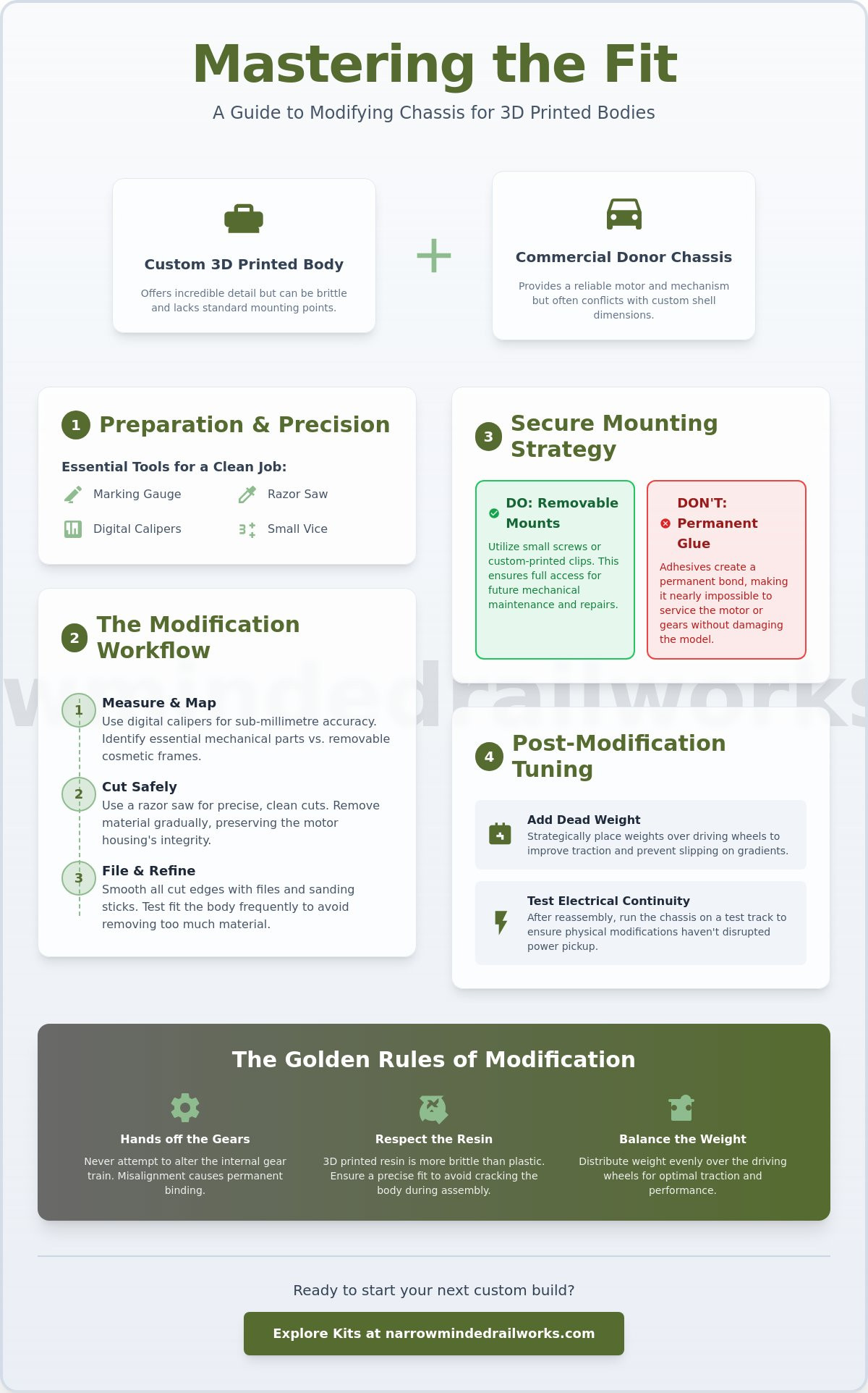
Key Takeaways
- Utilize digital calipers to achieve the sub-millimetre accuracy necessary for a seamless fit between commercial components and your custom 3D printed shell.
- Discover how modifying a chassis for a 3d printed body involves using a razor saw to remove cosmetic side-frames while preserving the structural integrity of the motor housing.
- Implement removable mounting strategies rather than permanent adhesives to ensure your locomotive or wagon remains fully accessible for mechanical maintenance.
- Enhance the performance of narrow gauge models by adding strategic dead weight to improve traction and testing electrical continuity after physical modifications.
Understanding the Chassis-to-Body Relationship
In narrow gauge modelling, the donor chassis acts as the mechanical heart of your project. While 3D printing allows for incredible detail, these shells are often designed with specific prototypes in mind that don't always align with off-the-shelf motor units. This discrepancy is the core of what is scratch building in the modern era; you're marrying two distinct technologies to create something unique. Modifying a chassis for a 3d printed body is usually necessary because commercial manufacturers prioritize their own rolling stock dimensions over universal compatibility. You'll often find that the "keep-out zones" where the motor and gears reside conflict with the internal bracing of a 3D print.
Before making your first cut, you must verify the wheelbase against your body blueprints. Misalignment here ruins the visual profile of a locomotive and can lead to wheels rubbing against the wheel arches. You need to identify which parts of the chassis are essential for movement and which are merely cosmetic. While a chassis might look bulky, much of that volume is often just plastic casing that you can carefully prune away to fit your narrow gauge shell.
To better understand how a chassis integrates with a custom shell, watch this helpful video:
Choosing Your Donor Chassis Wisely
Selecting the right foundation is vital for a successful build. Popular choices like the Kato 11-103 or Graham Farish units offer reliability, but you should check for electrical pick-up consistency before starting any work. If a unit stutters on a test track, it won't improve once it's tucked inside a resin shell. You also need to assess vertical clearance. Some 3D loco shells are low-profile and won't accommodate tall motor housings. For more detailed advice on selecting your first unit, read Your First OO9 Loco Kit: A Beginner’s Guide to Choosing and Buying.
Acknowledging Mechanical Constraints
While modifying a chassis for a 3d printed body allows for creative freedom, the internal gear train is a hard constraint. You should never attempt to alter the gears unless you're an expert, as even a tiny misalignment causes permanent binding. Instead, focus your efforts on thinning the plastic frame or removing decorative side-frames. Remember that 3D printed resin is often more brittle than injection-moulded plastic. It won't flex under pressure, so your chassis modifications must be precise to avoid cracking the body during assembly. Finally, consider weight distribution. Small-scale locomotives require significant "dead weight" over the driving wheels to maintain traction on uneven track or steep gradients.
Essential Tools and Measurement Techniques
Precision measurement is the foundation of any successful build. While many modellers rely on visual estimation, modifying a chassis for a 3d printed body requires a more rigorous approach to avoid permanent damage. Digital calipers are essential for this process. A basic set of digital calipers can be purchased for between $15 and $30, and they provide the sub-millimetre accuracy needed to map the internal dimensions of your resin shell. Just as automotive 3D printing relies on exact digital tolerances for structural components, your project depends on these measurements to ensure the mechanical unit sits perfectly within the decorative body.
Tool selection is equally critical. A standard hacksaw might seem like a versatile choice, but its coarse teeth often snag on thin plastic frames and cause unwanted fractures. Using a razor saw is the proactive solution; its fine blade allows for controlled, surgical cuts that leave a smooth finish. To maintain symmetry across the longitudinal axis, a marking gauge should be used to scribe lines on both sides of the chassis. This ensures that any material removed is balanced, preventing the locomotive from leaning or sitting "crabsided" on the track. For stability, always use a small vice with rubber jaw protectors. This setup prevents the donor unit from slipping while you work, which protects the delicate gear train from shock and vibration.
The Three Critical Dimensions
Before you begin any physical work, you must document three critical dimensions. First, measure the internal width of your 3D printed shell at its narrowest point. This determines how much you need to thin the chassis frame. Second, check the height of the motor housing relative to the boiler line or roofline. If the motor is too tall, you may need to design a custom interior or hide the protrusion with coal loads. Finally, calculate the "overhang" at both ends. You must ensure that your couplers have enough clearance to swing freely without hitting the buffer beams of the 3D print. If you need specialized gear to assist with these measurements, our selection of diorama tools and scenery can help equip your workbench for success.
Creating a Cutting Template
Creating a physical template prevents costly mistakes during the modification process. Apply high-visibility masking tape to the chassis and mark your "no-cut" zones where the motor mounts and electrical pick-ups reside. Transfer your caliper measurements directly onto the tape using a fine-liner pen. You should also mark a clear centre line on both the chassis and the 3D body. This allows you to align the two components squarely, ensuring that the wheels sit perfectly within the wheel arches and that the bogies have sufficient swing for tight narrow gauge curves.
Physical Modifications: Cutting, Filing, and Sanding
Once you've mapped your dimensions, the physical task of modifying a chassis for a 3d printed body begins. Most donor units, particularly those designed for N-gauge locomotives, feature moulded side-frames and cosmetic details that prevent a flush fit inside a narrow gauge shell. Removing these components is the first step in creating a functional foundation. While it's tempting to use side-cutters for speed, the uneven pressure can often fracture the main chassis block. A razor saw provides the surgical precision required to remove these details without compromising the internal motor mounts or electrical pick-ups.
Thinning a chassis frame is often necessary when fitting a bulky commercial unit into a slim OO9 or GN15 locomotive body. You must identify the structural ribs that hold the motor in place and avoid thinning these areas excessively. If you're working with a plastic frame, use a flat file to gradually reduce the width, checking the fit against your 3D print every few strokes. For die-cast metal chassis blocks, the process is more intensive. These blocks provide essential weight for traction, so you should only remove the minimum amount of material required for clearance. Always remove the motor and gears before working on metal blocks to prevent fine metal filings from entering the mechanism.
Safety is a priority when working with mixed materials. 3D printed resin produces a very fine, irritating dust when sanded or filed. You should always wear a mask and consider wet sanding to keep the particles out of the air. Similarly, the plastics used in commercial chassis can release fumes if they get too hot during cutting. Work at a steady pace and keep your workspace ventilated to ensure a safe modelling environment.
Surgical Cutting Techniques
A razor saw is your primary tool for clean, perpendicular cuts. If you're removing a large section of a plastic frame, you can use the score and snap method. Scribe a deep line with a sharp hobby knife, then apply gentle pressure until the plastic parts cleanly along the mark. When using rotary tools on metal blocks, heat build-up is a major concern. Excessive heat can melt the surrounding plastic components or damage the motor's magnets. Work in short bursts and allow the metal to cool between cuts. Finish all edges with a fine-grade file to ensure there are no burrs that could abrade the resin body over time.
Material Compatibility and Adhesives
Standard plastic cement works by melting styrene surfaces together, but it won't react with 3D printed resin. This is a common constraint that requires a proactive shift in your assembly strategy. For bonding resin to metal or ABS plastic, high-quality cyanoacrylate (CA) glue is the most effective solution. It provides a fast, strong bond that handles the vibrations of a running motor. If you're creating high-stress mounting points, two-part epoxy resin offers superior structural strength. Always test your chosen adhesive on a scrap piece of resin and a hidden part of the chassis to check for any unexpected chemical reactions before the final assembly.
Secure Mounting Strategies for 3D Printed Bodies
While permanent adhesives offer a quick fix, they often create long-term maintenance headaches. Gluing a body shell directly to a motor unit prevents you from performing essential tasks like lubricating gears or cleaning electrical pick-ups. Removable mounting is the superior choice for any serious project. When modifying a chassis for a 3d printed body, you should prioritize mechanical access by designing internal mounting blocks. These blocks can be integrated into the 3D model itself or added later using styrene sections. By utilizing the existing screw holes on your donor chassis, you ensure a secure fit that won't vibrate loose during operation.
Friction-fit solutions are sometimes used for lightweight wagons, but they frequently fail on locomotives. The constant vibration and torque from the motor can cause the body to "walk" off the frame over time. A mechanical fastener provides the stability needed for reliable running. If your donor chassis lacks convenient mounting points, you can glue plasticard spacers to the frame to create new platforms for screws. This proactive approach allows you to set the exact ride height needed for your specific prototype.
Screw-Mounting Perfection
Tapping threads directly into 3D printed resin requires a delicate touch. Resin can be brittle, so you must always drill a pilot hole slightly smaller than your screw diameter to prevent the material from cracking. If the shell wall is too thin, you can reinforce the area with a small block of styrene before tapping. You should also ensure that the screw heads are counter-sunk. This creates a flush, professional finish and prevents the hardware from interfering with the track or the internal gear mechanism. To find the right foundation for your next build, browse our collection of OO9 locomotive and wagon kits designed for easy assembly.
Coupler Integration
A successful coupler installation is the final step in a professional chassis modification. You must decide whether to mount the couplers to the chassis or the body. Chassis-mounted couplers are generally more robust, as they transfer the pulling force directly to the motor unit. However, body-mounted couplers often look more prototypical on narrow gauge models. You may need to refer to specific fitment guides, such as those for Quarry Hunslet couplers, to ensure your heights are consistent across your rolling stock. Always test the coupler swing on your tightest radius curves. If the coupler hits the buffer beam, it will lead to frequent derailments during shunting operations.
Post-Modification Fine-Tuning and Performance
Successfully modifying a chassis for a 3d printed body concludes with rigorous performance testing. While the physical surgery is complete, the model's reliability depends on meticulous fine-tuning of its mechanical balance. You should first verify electrical continuity using a multimeter or a dedicated test track. Chassis modifications can sometimes shift pick-up wipers or pinch internal wiring, leading to intermittent stalling. Identifying these electrical constraints early allows you to apply a proactive solution, such as re-tensioning wipers, before the body is permanently fitted. You also need to check for lateral stability. Narrow gauge locomotives often have a high centre of gravity, and any "body roll" on curves can lead to derailments if the weight isn't distributed evenly.
Once the mechanism runs smoothly, you can proceed to the final assembly steps. This phase ensures that the visual alignment matches the mechanical precision you've achieved. Before moving to the painting stage, confirm that the buffer heights are consistent and the body sits level on the track. These small adjustments distinguish a kit-bashed project from a professional-grade model.
Weighting for Traction
Resin bodies are inherently lightweight, which often results in poor traction for OO9 or GN15 locomotives. The proactive solution is to add strategic dead weight to the interior voids of your 3D print. You can use lead or tungsten shot to fill empty spaces in the boiler or water tanks. It's vital to balance this weight directly over the driving wheels to provide optimal grip. Ensure that loose weights are secured with PVA or epoxy to prevent rattles or balance shifts during transit. You must also verify that the weighting material doesn't foul any moving parts or block the motor's cooling vents, as restricted airflow can lead to overheating during long sessions.
The Test Run Protocol
A structured test run is essential for identifying "binding" in the gears that might not be visible at high speeds. For narrow gauge projects, slow-speed shunting reliability is the true mark of success. You should run the modified locomotive for at least 30 minutes in each direction to allow the gears and pick-ups to settle. During this time, observe the model on your layout's minimum radius curves. If the wheels rub against the 3D printed shell, you may need to perform additional thinning of the internal walls. Finally, check the buffer alignment with your existing rolling stock to ensure seamless coupling and uncoupling across your entire fleet.
Building Your Custom Fleet with Confidence
Commercial chassis are rarely a perfect fit for custom shells, but utilizing digital calipers and razor saws provides the surgical precision needed for a seamless marriage of parts. You've now learned how to prioritize mechanical access through removable mounting and how to enhance performance with strategic weighting. Mastering the process of modifying a chassis for a 3d printed body transforms a standard donor unit into a bespoke narrow gauge masterpiece that performs as well as it looks.
If you're ready to start your next project, browse our range of 3D printed locomotive kits designed for easy chassis fitting. Our models are designed specifically for popular Kato and Tsugawa chassis to minimize the need for complex alterations. We include detailed instructions with every kit to ensure you achieve a professional result, and we provide worldwide shipping for all narrow gauge modellers.
With these technical skills at your disposal, your workshop is now equipped to produce smooth-running, highly detailed models. It's time to take your measurements and start building the unique railway you've always envisioned.
Frequently Asked Questions
Can I use a standard N gauge chassis for an OO9 3D printed body?
Yes, N gauge chassis are the standard choice for OO9 modelling because both share a 9mm track gauge. While the body scales differ, the mechanical foundations are compatible with narrow gauge locomotive kits. You must verify the wheelbase dimensions against your 3D printed shell to ensure the axles align with the wheel arches. If the alignment is slightly off, you can often trim the internal resin bracing to provide the necessary clearance.
What is the best glue to bond 3D printed resin to a plastic chassis?
High-quality cyanoacrylate (CA) glue is the most reliable choice for bonding resin to plastic or metal. Standard plastic cement won't work because it cannot chemically melt the surface of 3D printed resin. For high-stress mounting points, a two-part epoxy resin is the proactive solution. It provides a gap-filling, vibration-resistant bond that ensures the body remains secure even during the torque shifts of heavy shunting work.
How do I shorten a commercial chassis that is too long for my kit?
Shortening a chassis involves cutting the main frame and driveshaft, which is a complex task with a high risk of mechanical failure. A better approach is to select a donor unit that matches your required wheelbase from the start. If you must proceed, use a razor saw for surgical cuts and a small vice for stability. You must maintain exact gear spacing to prevent the motor from binding or stripping the teeth during operation.
Do I need to prime the chassis before mounting the 3D printed body?
Priming the entire chassis isn't mandatory, but applying a light coat to modified areas is a helpful step. When modifying a chassis for a 3d printed body, filing and sanding can leave burrs that interfere with a flush fit. A quick spray of primer highlights these imperfections, allowing you to smooth them out before final assembly. It also provides a uniform surface if you need to paint the chassis to match your locomotive's livery.
Will modifying my chassis void the manufacturer warranty?
Yes, any physical modification like cutting, filing, or soldering will void the manufacturer's warranty. Because you're altering the structural integrity of the unit, the manufacturer won't cover mechanical or electrical failures. To manage this constraint, you should run the chassis for 30 minutes in each direction before starting any work. This test run ensures the motor and gears are reliable before you commit to permanent modifications.
How do I add weight to a 3D printed locomotive without affecting the motor?
You can add weight by filling the hollow voids of the 3D printed boiler or side tanks with lead or tungsten shot. Secure these weights with PVA glue to prevent them from shifting or rattling. Always place the weight directly over the driving axles to maximize traction. This proactive placement improves grip on the rails without putting unnecessary vertical strain on the motor bearings or the delicate gear train.
What should I do if my 3D printed body is slightly warped?
Minor warps in resin can often be corrected by soaking the body in warm water for several minutes until the material becomes pliable. Gently bend the resin back into alignment and hold it against a flat surface until it cools. If the warp is permanent, you can sand the mounting blocks on the chassis to compensate. This ensures the locomotive sits squarely on the track despite any slight geometric imperfections in the shell.
Can I use DCC decoders with a modified chassis?
Most modified chassis can accommodate DCC decoders if there's sufficient internal volume within the 3D printed shell. While our business focuses on the kits rather than digital systems, you should check the decoder dimensions against your internal measurements early in the build. When modifying a chassis for a 3d printed body, plan your wire routing carefully to avoid pinching cables between the motor housing and the resin walls during final assembly.