

What if the instruction sheet isn’t a page of rules, but a sequence of small decisions? Learning how to read model kit instructions can feel daunting when symbols, part labels and diagrams are unfamiliar, especially when you’re unsure which assembly comes first. You don’t need to understand everything at a glance. You need a method for checking each step before you act.
This guide shows you how to scan the sheet before assembly, find the parts and symbols a step refers to, and follow diagrams while checking orientation. You’ll also learn why instruction symbols can vary between manufacturers, so the kit’s own legend and notes matter more than assumptions based on another model.
We’ll work through assembly sequences, subassemblies and common points where it pays to pause before cutting, gluing or fitting a part. You’ll also see how to compare the instructions with kit-specific information, so you can tell what the steps cover and identify anything to resolve before continuing. Take it one decision at a time, and the sheet becomes easier to follow.
Key Takeaways
- Read model kit instructions as a sequence of decisions, rather than trying to interpret the whole sheet at once.
- Match step numbers and diagrams to part identifiers, and check orientation before joining pieces.
- Use the kit’s own symbol key; icons and conventions can vary between manufacturers.
- Read one step ahead to prepare, but complete only the current instruction before moving on.
- Compare the product listing with the instructions to distinguish supplied parts from items the assembly may require separately.
How to Read Model Kit Instructions Before You Start Building
A new instruction sheet can look unfamiliar, but you don’t need to understand every mark immediately. Manufacturers use different layouts, labels and drawing conventions, so experience with one type of kit may not translate directly to another. Treat the sheet as a sequence of decisions: identify the next action, confirm which parts it refers to, then check the diagram before proceeding.
An instruction sheet is the kit’s step-by-step assembly reference, showing what to do, which parts are involved and how each stage connects to the next. Use it to understand the sequence, not just to identify parts in a picture. For background on the range of models and techniques, see this Model building overview on Wikipedia, then let the instructions for your specific kit guide the build.
What to identify on the instruction sheet first
Before removing parts from their packaging, take a moment to orient yourself. Look for the kit name, sheet title, page numbers and revision information, if present. These details help you confirm that you’re using the right instructions and can help distinguish an updated sheet from an older copy. Then locate any separate parts inventory and compare it with the kit’s stated contents.
- Check whether pages are numbered and meant to be followed in sequence.
- Look for a separate parts list, notes page or legend.
- See whether painting guidance is provided separately from assembly diagrams.
- Notice warnings or preparation notes before starting a step.
A contents list and an assembly sheet answer different questions: one describes what should be supplied, while the other explains how the depicted parts fit together. If a diagram seems to show an item you can’t find, pause and compare it with the kit information. The drawing may show an item for reference or a material that isn’t part of the kit.
Why model kit instructions differ
There isn’t one universal visual language for every model kit. A manufacturer may use its own symbols, arrows, line styles or shorthand, and a railway kit may present information differently from an aircraft, car or figure kit. Don’t assume a Gunpla symbol applies to a railway kit. When shown, symbols for cutting, adhesive, decals or assembly order should be read using that kit’s own legend and notes.
Some kits use a broad overview followed by close-up steps; others place notes beside each drawing or on a separate page. Read the sheet’s key before interpreting marks, and don’t treat part labels as instructions about when to assemble them. If a revision number appears, make sure it matches the kit information you’re using. When something remains ambiguous, stop before cutting or joining parts and recheck the relevant page.
Resin parts are delicate, so handle them carefully by thicker sections and avoid dropping them. Parts are cleaned and UV-cured before dispatch, though fine support marks or layer lines may remain. If needed, gently sand with fine-grit paper from 800 to 1200 grit. Many modellers may wish to give the parts a quick wash in mild soapy water before priming. We cannot be held responsible for breakages once your item has arrived. If the piece is broken in the post, please provide images and we will see what we can do to help.
How to Read Model Kit Diagrams, Parts, and Assembly Order
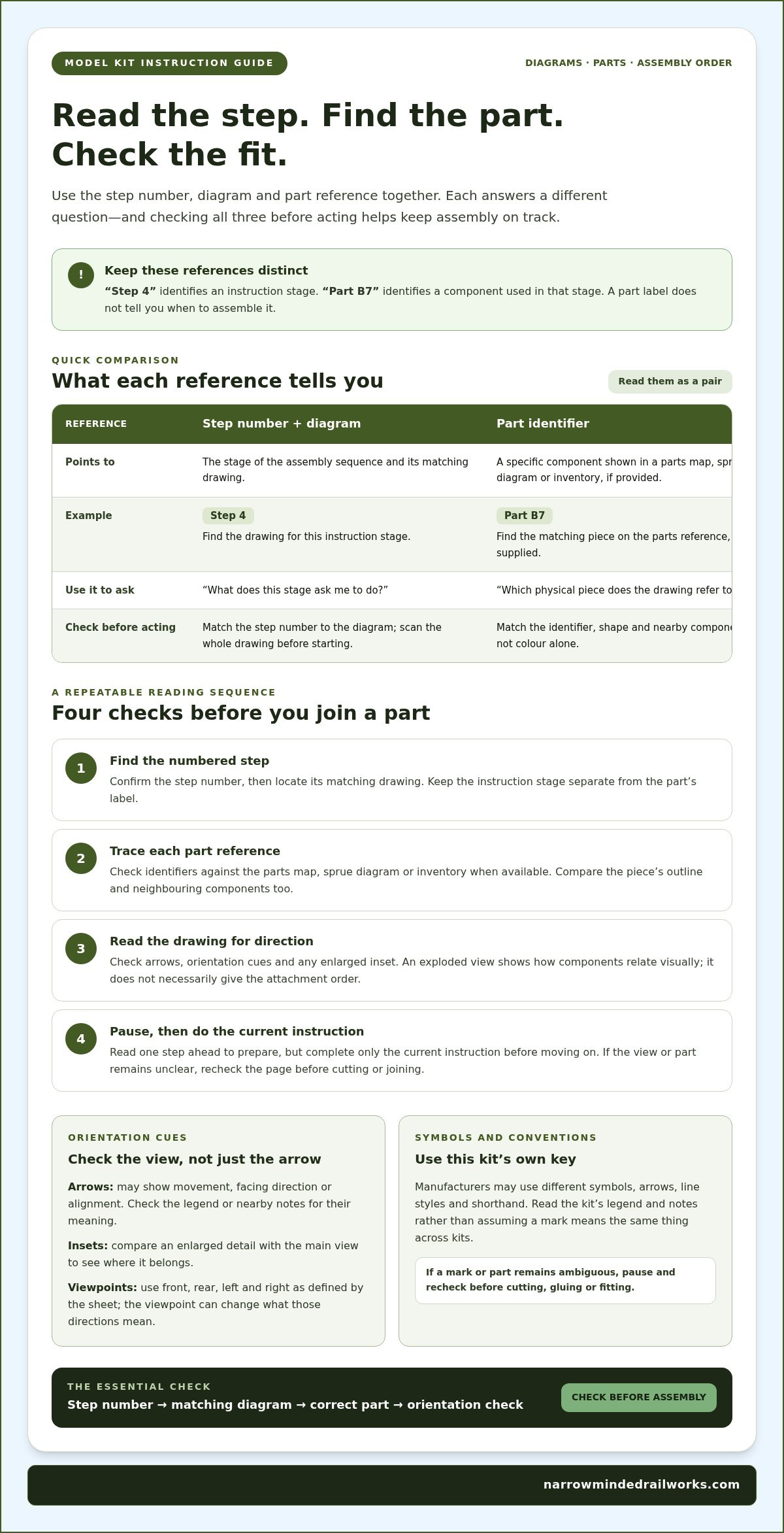
Once you’ve found the right page, read the step number, drawing and part references together. Match each step number to its diagram before removing or joining parts. This simple pause helps prevent a common mix-up: treating a part label as if it tells you when to assemble that piece. In a generic example, “Step 4” identifies an instruction stage, while “Part B7” identifies a component used in that stage.
To understand how to read model kit instructions, trace the information in a consistent order. Find the numbered step, locate its matching drawing, then check each part identifier against the parts map, sprue diagram or inventory, if one is provided. The drawing shows what the step asks you to do; the label tells you which piece to find. Use both references together when the sheet provides them.
Follow step numbers, arrows, and orientation cues
Start with the step number, then scan the entire diagram before acting. Arrows may show a part moving into position, the direction it faces or how two edges align. Their meaning can vary, so check the legend or nearby notes rather than assuming every arrow means “attach here”. If the drawing includes an enlarged inset, compare it with the main view to see where the detail sits.
Exploded views separate components visually to show how they relate before fitting. They don’t necessarily mean every part should be attached in the order it appears on the page. Look for orientation cues such as a front or rear view, a marked top surface, or a reference feature. Use front, rear, left and right only as the sheet defines them, since the viewpoint can change which side those directions describe.
Match part identifiers to the correct pieces
If parts are numbered or lettered, find the same identifier on the parts map or sprue diagram when provided. A label such as “B7” can point to a specific piece on a frame, while “Step 4” points to a stage in the instructions. Keep those references distinct. If the part map uses a different view from the assembly drawing, compare the shape and nearby components as well as the identifier.
Before picking up a piece, confirm that its outline, colour or position matches the drawing. Colour can help distinguish parts in colour illustrations, but it isn’t reliable on its own, particularly in monochrome diagrams. Check neighbouring components, too: a part’s shape and its position beside another piece can confirm whether you’ve found the right one. If identifiers look similar or a view is unclear, pause and compare the other diagrams before cutting or joining anything.
Practise checking step references against the parts shown on a narrow-gauge build, such as these OO9 locomotive kits. The aim isn’t to memorise a universal diagram style, but to verify each drawing against the labels and orientation cues on that kit’s own sheet.
How to Interpret Model Kit Symbols Without Guessing
Instruction symbols can save space, but they can also cause confusion if you assume an icon means the same thing across every kit. There’s no single symbol key that applies to all manufacturers. A mark used in one Gunpla manual, for example, shouldn’t automatically be read the same way in a railway kit. Start with the legend on the specific instruction sheet, then use the nearby drawing and notes to understand what the mark means in context.
The examples below describe common types of marks you may encounter, not a universal code. A kit may use different artwork, wording or no symbol at all for the same action.
Common instruction marks and what they may indicate
| Symbol or reference | Likely instruction | Kit-specific caveat |
|---|---|---|
| Glue or adhesive mark | Apply adhesive at a joint or contact point. | Check the legend and notes for where, and whether, adhesive is called for. |
| Cut line, scissors or blade mark | Separate a piece or remove material at the indicated point. | Confirm exactly what the line points to before cutting; it may refer to a particular attachment or edge. |
| Sticker number | Find a numbered sticker and its placement reference. | Match the number to the kit’s sticker sheet or placement guide, if supplied. |
| Decal number | Locate a numbered decal and its position in the diagram or guide. | Sticker and decal references may use different sheets or numbering systems. |
| Assembly-order mark | Follow a specified sequence or complete one part before another. | Check the legend and adjacent steps to see which stage depends on the earlier one. |
These marks are useful only when you can connect them to the kit’s own references. A number beside a decal may identify its placement, while a number in a step box may indicate the assembly stage. Read labels in context rather than treating every number or icon as a direct instruction.
What to do when a symbol is unclear
Pause before acting. Compare the unfamiliar mark with the main diagram, any enlarged view, nearby notes and the parts list. Ask what the drawing appears to show, which part it points to, and whether the legend supports that interpretation. If those clues don’t agree, don’t guess.
In particular, hold off on cutting, gluing or trimming until the intended action and location are clear. A small mark can be easy to misread when it sits beside several parts or lines. Recheck the specific kit documentation rather than borrowing conventions from another hobby or manufacturer. This is a practical part of learning how to read model kit instructions: verify unfamiliar marks against the sheet in front of you, and continue only when the next action makes sense.
A Step-by-Step Method for Following Model Kit Instructions
A repeatable routine turns a busy instruction sheet into manageable actions. Read one step ahead so you can prepare for what follows, but don’t assemble beyond the current instruction. That gives you context without encouraging you to skip a check or join parts too early.
Prepare the workspace and check the next steps
Set out the instruction sheet where you can refer to it without moving parts around. Keep the parts map or inventory nearby, and organise small pieces so their identifiers remain visible. At each stage, gather only the parts needed for the current step. This limits mix-ups and makes it easier to return an unneeded piece to the right place.
Before starting, read the current instruction and its immediate follow-up. The next step may show that a component needs to face a particular way or remain accessible, but it isn’t permission to build ahead. Use the preview to understand what the current action needs to leave ready.
Dry-fit, act, and verify each stage
- Identify the step. Match its number to the correct drawing, then find each part identifier on the parts map or kit pieces.
- Check orientation. Compare the part’s shape and features with the illustration. Use front, rear, left or right only as defined by the sheet.
- Dry-fit where appropriate. Bring the pieces together without adhesive or another irreversible action. Compare their position with the diagram and check that edges, locating features or holes align as shown. If the fit or orientation seems wrong, stop and recheck the references.
- Follow the stated action. Once the parts and their positions make sense, carry out only what the current step instructs. Don’t infer extra cutting, trimming or joining from the appearance of the picture.
- Verify the result. Compare the assembled stage with the drawing before moving on. Check its orientation and note which parts or features must remain accessible for the next instruction.
Pause after each subassembly, especially where several parts meet or the sheet uses an inset to show a close-up. A quick comparison can catch a reversed component or a missed part while the step is still straightforward to review. If your result differs from the illustration, don’t force the next piece into place. Revisit the part identifiers, arrows and notes first.
This method is a practical way to approach how to read model kit instructions: prepare, identify, check, act and verify. Specialist painting, weathering and support-mark removal techniques are separate from assembly, so use appropriate finishing guidance rather than improvising mid-build.
Ready to put the method into practice? Explore narrow-gauge model kits and match each assembly step to its parts and diagrams.
Use a Kit Listing to Confirm What the Instructions Actually Cover
Instructions explain how to assemble the parts shown, while a product listing describes what the kit contains and what needs to be sourced separately. Compare both before interpreting a diagram. This helps you tell whether an illustrated component is supplied, shown for reference, or part of a later assembly stage. It also gives you a clear baseline for checking the contents before you begin.
Check a narrow-gauge kit’s contents before interpreting its steps
The OO9 Peckett & Sons Narrow Gauge kit is listed at £25.00. Its stated contents are a resin body, clip-on chassis frame, two 3D-scanned crew figures, and two Peregrine couplers. Use that list alongside the instructions: if a drawing shows one of these pieces, compare its shape and label with the listed contents before deciding how the step applies.
Pay particular attention to the distinction between the supplied clip-on chassis frame and the KATO 11-109 chassis. The KATO 11-109 chassis is not included; it is shown for information only. The clip-on frame is a listed kit component, but it isn’t the separately sourced KATO chassis. Keeping those items distinct prevents a reference image or assembly diagram from being mistaken for a complete contents list.
The listing also helps set expectations for the build. The kit is supplied unpainted, unprimed and unassembled. Read the product contents to establish what you have, then use the instruction sheet to determine how its components are assembled. Don’t assume that a pictured item, paint finish or assembly aid is included unless the listing says so.
Prepare resin parts carefully and set realistic expectations
Resin parts are delicate. Handle them carefully by thicker sections and avoid dropping them. Parts are cleaned and UV-cured before dispatch, though fine support marks or layer lines may remain. If marks need attention, gently sand with fine-grit paper from 800 to 1200 grit. Many modellers may also wish to give the parts a quick wash in mild soapy water before priming. These are preparation considerations, not extra assembly steps: follow the instructions for fitting parts and take care when preparing the material.
Packaging details can also help you understand how parts are protected in transit. Outer packaging is partly made from recycled materials and is fully recyclable; interior packing is acid-free and made from approximately 99% recycled pulp fibres. Orders are dispatched by Royal Mail, with worldwide shipping options available.
For clarity, the breakage policy states: “We cannot be held responsible for breakages once your item has arrived. If the piece is broken in the post, please provide images and we will see what we can do to help.”
Checking the listing alongside the diagrams makes how to read model kit instructions more practical: you can distinguish what the sheet asks you to assemble from what the kit supplies. Explore narrow-gauge model kits and review each kit’s stated contents before planning your build.
Put Your Next Build in Motion
Each kit has its own drawing style and set of parts, so approach a new instruction sheet without assuming it follows conventions you’ve seen elsewhere. Use the product details and diagrams together, and take time to check before making a change that can’t easily be undone. That steady approach is the real skill behind how to read model kit instructions with confidence.
Narrow Minded Railworks makes hand-crafted 3D-printed narrow-gauge kits in the UK for OO9, GN15 and 16 mm layouts. For a specific example, the OO9 Peckett & Sons Narrow Gauge kit is listed at £25.00 and contains a resin body, clip-on chassis frame, two 3D-scanned crew figures, and two Peregrine couplers. These details apply to that kit, not every model.
Choose a project for your next careful build: Explore Narrow Minded Railworks kits, then follow the instructions one step at a time.
Frequently Asked Questions
How do I read model kit instructions if I am a complete beginner?
Begin by confirming that the instruction sheet matches your kit, then work through one numbered stage at a time. To practise how to read model kit instructions, trace a step number to its drawing, then match each part label to the piece it identifies. You don’t need to memorise the whole sheet. If a symbol or viewpoint is unclear, pause and check the notes before handling the part.
Do all model kit instructions use the same symbols?
No, symbols and drawing conventions can vary by manufacturer and kit type. A mark resembling glue, a cut line or a decal reference may look familiar, but check the sheet’s legend and nearby notes to confirm its meaning. For example, don’t assume an icon from a figure kit means the same thing in a railway kit. Read the symbol in the context of its diagram and the action shown.
Can I build a model kit without understanding the instructions’ language?
Sometimes diagrams and part numbers help you follow a build, but they can’t guarantee that every instruction or warning will be clear without translation. Use visual references to identify the parts and possible sequence, then look up manufacturer-specific symbols in the kit’s key. Translate written cautions you don’t understand before acting. If a note could affect cutting, fitting or joining, pause until its meaning is clear rather than relying on a guess.
What should I do if a model kit instruction page is missing?
Check the packaging and any remaining paperwork for the manufacturer’s name, product identifier and revision details. Use those details to find the maker’s official instruction source, and compare the document title or identifiers with your kit before following it. Similar models can have different components or assembly stages, so a manual that looks close may still be wrong. Don’t substitute another kit’s sheet unless you can establish that it matches your model.
Should I remove every part from the sprue before following the instructions?
Usually, prepare only the pieces needed for the current stage, unless your kit’s instructions direct you to do otherwise. Keeping other parts attached, or arranging them so their labels remain visible, can make them easier to identify later and reduce the chance of mixing similar pieces. Before cutting, compare the part with the drawing and its identifier. If either the piece or its orientation is uncertain, leave it in place while you check.
What does it mean when a model kit diagram shows an extra part?
An apparent extra may be an alternate option, an unused component or a piece intended for a different configuration, but the specific diagram determines which. Look for callout letters, notes such as “not used”, and references to other steps; then compare these with the parts list. A component visible beside the main assembly isn’t necessarily required in that stage. Don’t assume it’s missing or spare until the kit documentation supports that interpretation.